This blogger chronicles the building of a Cessna 172 simulator panel using MS Flight Simulator 2004, joystick peripherals, and actual Cessna parts. The aim is to construct a simulator close enough in dimensions to the real airplane to serve as a humble beginning to eventual real pilot training.

Sunday, October 15, 2006

Cessna 172 Simulator Panel - MS FS 2004

CH YOKE EXTENDED
Last entry, we left our modified CH yoke setting with its new extension.
Obviously, a very technical task since accurate alignment is essential.

BEFORE


AFTER

Side view
As you can see, I left the switches out to extend the wires and place them on the panel as needed.
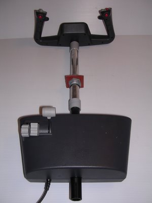


Top view


PANEL PROGRESS
Continuing on the theme of portability with facility to disassemble, we begin thinking of the actual table that will hold the panel.
We find an old foldout table gathering dust at home that, although not perfect, will do the job.
Dad and I head to the “toy store” (AKA Home Depot) to find some hardware to hold the panel.
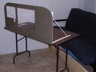


Table is a bit high (floor to panel) vs. the actual dimensions of the 172.   None-the-less, we can either cut a small portion of ea leg to lower the panel OR use the panel's current height to simulate some distance off the ground as if to be sitting on the landing gear. We'll see.
Sunday, October 01, 2006

Cessna 172 Simulator

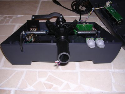
CUTTING THE CH YOKE SHAFT:
Dad had a tube cutter that fit the 1” diameter of the yoke shaft.  The cut is made at the closest point to the yoke itself allowing equal space on either side of the cut shaft to fit couplers without hindering the shaft's full range of motion.


Web photo.  Sorry, don't remember web site.

WIRES:
Once the Yoke shaft is cut, BE EXTREMELY CAREFUL not to cut the entire black cable (which carries 11 wires) all at once because it includes 4 pairs of like colors.
  • 2 Black
  • 2 White
  • 2 Purple
  • 2 Orange
  • 1 Red
  • 1 Blue
  • 1 Green


PVC PIPE PREP:
After careful measurement of all pertinent distances, including the shaft’s forward and aft displacement, we cut the ¾” PVC pipe to the length we need and cover it with Silver Air-Duct tape to make it look like an aluminum pipe.


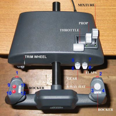
CH YOKE  -  BUTTON ASSIGNMENT CHECK:
We then run extensions through the PVC pipe, couplers, and faux shaft support and solder the ends to their respective wires.
Before we epoxy all the PVC, Couplers, and Yoke shafts, I hook up the CH Yoke to the CPU and test all button functions and assignments. They all work fine.

Web photo: Michael R. Stiteler (unmodified yoke)

All parts are now setting with fresh epoxy.
I will post the pics of the yoke with extended shaft once epoxy sets.