Cessna 172 Simulator Panel - MS FS 2004
CH YOKE EXTENDED
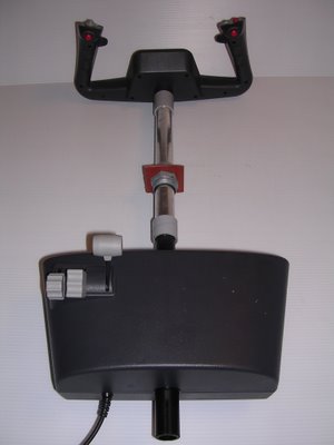
Last entry, we left our modified CH yoke setting with its new extension.
Obviously, a very technical task since accurate alignment is essential.
BEFORE

AFTER

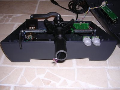
Side view
As you can see, I left the switches out to extend the wires and place them on the panel as needed.
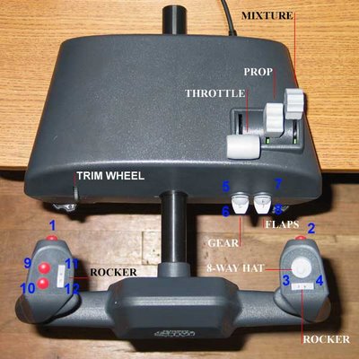
Top view
PANEL PROGRESS
Continuing on the theme of portability with facility to disassemble, we begin thinking of the actual table that will hold the panel.
We find an old foldout table gathering dust at home that, although not perfect, will do the job.
Dad and I head to the “toy store” (AKA Home Depot) to find some hardware to hold the panel.
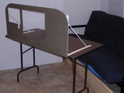
Table is a bit high (floor to panel) vs. the actual dimensions of the 172. None-the-less, we can either cut a small portion of ea leg to lower the panel OR use the panel's current height to simulate some distance off the ground as if to be sitting on the landing gear. We'll see.
posted by Cessna 172 Simulator Panel at 9:25 AM
|
2 comments
![]()